
Spindle Motor for CNC Router: Installation, Wiring, and Getting It Running
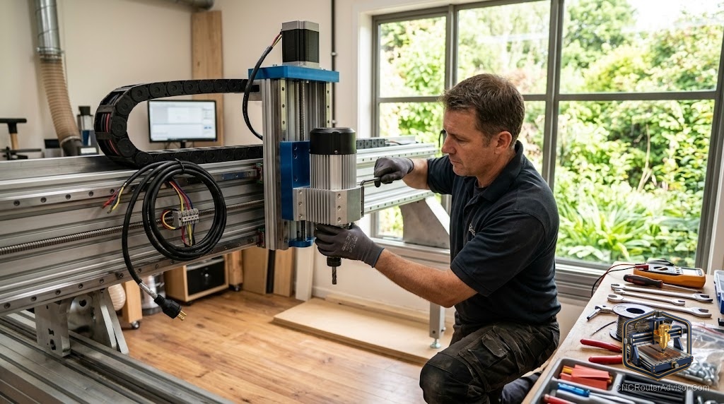
Buying a new spindle motor is the easy part. Getting it running cleanly, electrically safe, and properly tuned is where most people hit the wall. The spindle motor is the heart of the CNC router, and upgrading from a trim router to a proper spindle motor is one of the most satisfying upgrades in the hobby, but it is also one that requires you to understand a few things that the product listing will not explain. This guide is the explanation the listing does not give you.
A spindle motor for a CNC router is a purpose-built brushless motor designed to hold cutting bits at precise, continuously variable speeds for extended duty cycles. Unlike a trim router (a repurposed handheld tool), a dedicated CNC spindle motor is matched with a VFD (variable frequency drive) for electronic speed control, runs with less tool runout, and is designed for the continuous rotation that production CNC routing demands. The motor and VFD function as a matched pair: you do not buy one without the other.
The short guide to getting it running: match the motor’s power rating and voltage to a compatible VFD, wire the motor to the VFD correctly (U, V, W leads plus ground), program the VFD’s key parameters (motor frequency, max RPM, acceleration ramp), wire the VFD’s control signal to your CNC controller for speed commands, and verify rotation direction before cutting. That sequence, done carefully, is the whole installation. Done carelessly, it is the most common source of spindle problems.
Choosing the motor: power, cooling, and collet
The most common upgrades are 1.5 kW and 2.2 kW motors, and the choice between them is straightforward: 1.5 kW handles light to medium wood and plastic work on most desktop machines, while 2.2 kW gives more headroom for harder materials, deeper passes, and larger bits. On a machine with a light frame, a 2.2 kW motor does not produce better cuts than a 1.5 kW motor if the frame flexes under the load, so match motor power to your frame’s ability to use it.
Cooling matters for how long and how hard you run. Air-cooled motors have an integrated fan and are simpler to install, but they direct the cooling airflow outward, which can push chips back toward the work surface, and they are louder than water-cooled alternatives. Water-cooled motors circulate coolant through the spindle body, running dramatically quieter and tolerating longer continuous runs, but they require a pump, reservoir, and coolant lines, adding installation complexity. Most small shops and serious hobbyists start with air-cooled and upgrade to water-cooled when noise or duty cycle becomes a constraint.
Collet choice: purpose-built spindle motors typically use ER collets, with ER11, ER16, and ER20 being the common sizes. ER20 is the most versatile for prosumer work, accepting 1/4 inch, 6 mm, and larger shank bits. Match your collet size to the shank sizes of the bits you use most.
The VFD: the part most guides underexplain
The VFD (variable frequency drive) is not an optional accessory. It is the control system for the motor, converting fixed mains frequency to variable frequency to set the motor’s RPM electronically. Without a VFD, the motor is a brick. The VFD must be rated for the motor’s power (a 2.2 kW motor needs a 2.2 kW or larger VFD), matched in voltage (single-phase 220V is common for hobby use; three-phase for industrial), and configured to match the motor’s electrical characteristics.
VFD programming intimidates beginners, but only a handful of parameters need adjustment for a basic CNC installation. The critical ones are: motor rated frequency (typically 400 Hz for CNC spindles, not the standard 50 or 60 Hz), maximum output frequency, motor rated voltage and current (from the motor nameplate), acceleration and deceleration ramp times (too fast strains the motor and machine frame), and the control signal input (0 to 10 V analog or RS-485 for integration with your CNC controller).
Set these wrong and the motor will not run to its rated RPM, may run hot, or may start and stop erratically. Set them correctly and the motor runs cleanly from startup to full speed, responds to your controller’s speed commands, and ramps smoothly. The motor’s nameplate and the VFD’s manual are the two documents you need. Read both before wiring.
Wiring: do this correctly or do not do this at all
CNC spindle motors run at 220V or higher, and the VFD draws significant current. Wiring errors are not a nuisance, they are a safety hazard. If you are not comfortable with mains electrical work, hire an electrician for the mains side and handle only the signal wiring yourself.
The motor connects to the VFD’s output terminals labeled U, V, and W (three-phase output to the motor), plus a ground. The mains input connects to the VFD’s input terminals, which vary by VFD model. The control signal from your CNC controller (a 0 to 10 V analog signal or RS-485 depending on your controller and VFD) connects to the VFD’s control terminals to allow the controller to set speed. An emergency stop signal should also be wired through the VFD’s enabling circuit so an e-stop kills the spindle.
Label every wire before you connect it. Check the VFD manual’s connection diagram against your wiring before powering on. Run the motor unloaded first (no bit, no material) to verify rotation direction (clockwise when viewed from the collet end) and smooth operation before making a cut.
Rotation direction check is mandatory. Wiring two of the three motor leads in reverse order reverses the motor’s direction. Running a cutting bit backward dulls it instantly and throws chips in the wrong direction. Swap any two motor leads at the VFD output (not at the motor) to reverse if needed.
Mounting and tramming
The motor mount needs to hold the spindle body firmly without play and keep the spindle axis truly perpendicular to the machine bed (tramming). A loose mount or a tilted spindle means the bit cuts at an angle, leaving ridged floors in pockets and inaccurate wall depths. Use a dial indicator to tram the spindle after mounting, and check it again after the first few hours of running once the mount has fully settled.
Frequently asked questions
Do I need a VFD for a CNC spindle motor? Yes, always. The VFD is the control system for the motor and is required for it to run at variable speeds. Motor and VFD are a matched pair.
What VFD parameters do I need to set? At minimum: motor rated frequency (typically 400 Hz for CNC spindles), maximum output frequency, motor rated voltage and current, acceleration/deceleration ramp times, and control signal input type.
Why is my spindle running in the wrong direction? Two of the three motor leads (U, V, W) are swapped. Swap any two of the three motor leads at the VFD output to reverse direction.
What is tool runout and why does it matter? Runout is how much the bit tip wobbles off-center during rotation. Less runout means cleaner cuts and longer bit life. Purpose-built spindles with ER collets have tighter runout than trim routers.
How do I know what power VFD to buy for my spindle? Match or exceed the motor’s rated power. A 2.2 kW motor requires a VFD rated at 2.2 kW or above in the same voltage class.
Is water cooling worth the complexity? For noise-sensitive shops or long continuous runs, yes. For most small shops running several hours a week, an air-cooled spindle is simpler and sufficient.
References
- Spark Robotic, CNC Spindle Wiring and Troubleshooting Guide — https://www.sparkrobotic.com/pages/trouble-shooting
- WorkshopCalc, “CNC Router Spindle Selection” — https://workshopcalc.com/guides/best-cnc-routers
- CNCCookbook, “CNC Spindle Motor and VFD Guide” — https://www.cnccookbook.com/cnc-router/