3D Model CNC Router: Getting from a Digital Shape to a Finished Carving
The preview in your CAM software looks perfect. The simulation shows exactly the carved result you’re imagining. Then the machine starts, the roughing pass runs clean, and the finishing pass begins - and somewhere in those 4 hours of ball-nose traversal, the result goes from perfect to slightly off. Investigating afterward, it usually comes down to one setting: the stepover was too large, or the mesh had a problem that the simulation smoothed over.
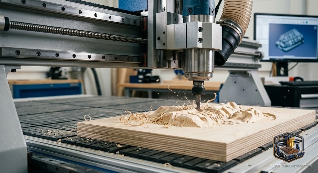
Using a 3D model with a CNC router means importing a three-dimensional file into CAM software, generating roughing and finishing toolpaths that follow the model’s surface contours, and cutting that geometry into a physical material. The quality of the result depends on mesh quality, CAM settings, tooling, and machine rigidity acting together.
The direct answer: import your STL into Aspire or Carveco, set up a roughing pass with a flat end mill (6mm or 1/4-inch) and a finishing pass with a ball-nose end mill (3mm to 6mm) at 8 to 12% stepover, verify that Z depth fits your machine’s travel, and run the simulation before committing material.
The Workflow Step by Step
1. Source the STL
Downloaded from Cults3D or Etsy, created in Aspire or Blender, or captured with a 3D scanner. The model must be watertight (no mesh holes) and free of undercuts for 3-axis cutting.
2. Import and Scale
Import into your CAM software. Set dimensions to match the intended carving size. Verify maximum relief depth is within machine Z travel minus tool holder clearance.
3. Configure Roughing Pass
Flat or bull-nose end mill, 6mm or 1/4-inch diameter. Cuts the geometry in horizontal layers, leaving a stepped surface. Feed rate can be aggressive; surface quality doesn’t matter here.
4. Configure Finishing Pass
Ball-nose end mill, 3mm to 6mm. Stepover 8 to 12% of tool diameter. This pass defines the final surface. Smaller stepover = smoother surface + longer cutting time.
5. Post-Process and Cut
Export G-code via the GRBL or appropriate post-processor. Send through Candle, UGS, or gSender. Watch the first few minutes to confirm the machine is executing correctly.
Common Problems and Fixes
Non-manifold mesh: Holes or self-intersections in the STL. Fix with Meshmixer Inspector before importing.
Undercuts: Geometry that faces back toward the table. These areas remain uncut, leaving flat spots. Check the model for overhangs before committing material.
Excessive polygon count: Very high-resolution scans slow CAM significantly. Reduce polygon count in Meshmixer’s Remesh function before importing.
Surface ripple on finished carving: Stepover too large, or machine gantry flex. Reduce stepover or check gantry tram and wheel tension.
Verdict
The model-to-cut workflow is consistent: clean STL, import and scale, roughing pass, finishing pass at 8 to 12% stepover. Mesh problems are fixable before cutting. The most common errors are setting the stepover too large and ignoring undercuts. Both are visible in the CAM simulation if you look for them.
- Import STL, verify scale and depth, set up two-pass strategy
- Roughing: flat end mill removes bulk; finishing: ball-nose traces final surface
- 8 to 12% stepover on finishing pass controls surface quality
- Fix non-manifold mesh issues with Meshmixer before importing
FAQ
What STL quality is needed for CNC routing? Watertight (no holes), no self-intersections, no undercuts. Meshmixer’s Inspector tool checks all three.
What stepover for 3D CNC finishing? 8 to 12% of the ball-nose diameter. Finer stepover = smoother finish + more cutting time.
What causes flat spots in a 3D CNC carving? Undercuts in the model. Any geometry facing back toward the table is skipped by a 3-axis machine.
Can I use Fusion 360 to generate 3D toolpaths for wood? Yes. Fusion 360’s parallel finishing and scallop strategies work well for wood. Choose a GRBL post-processor for your machine.
References
- Meshmixer: meshmixer.com
- Vectric Aspire: vectric.com
- Cults3D: cults3d.com