2D Router CNC: How to Set Up and Run a 2D Program From Design to Finished Part
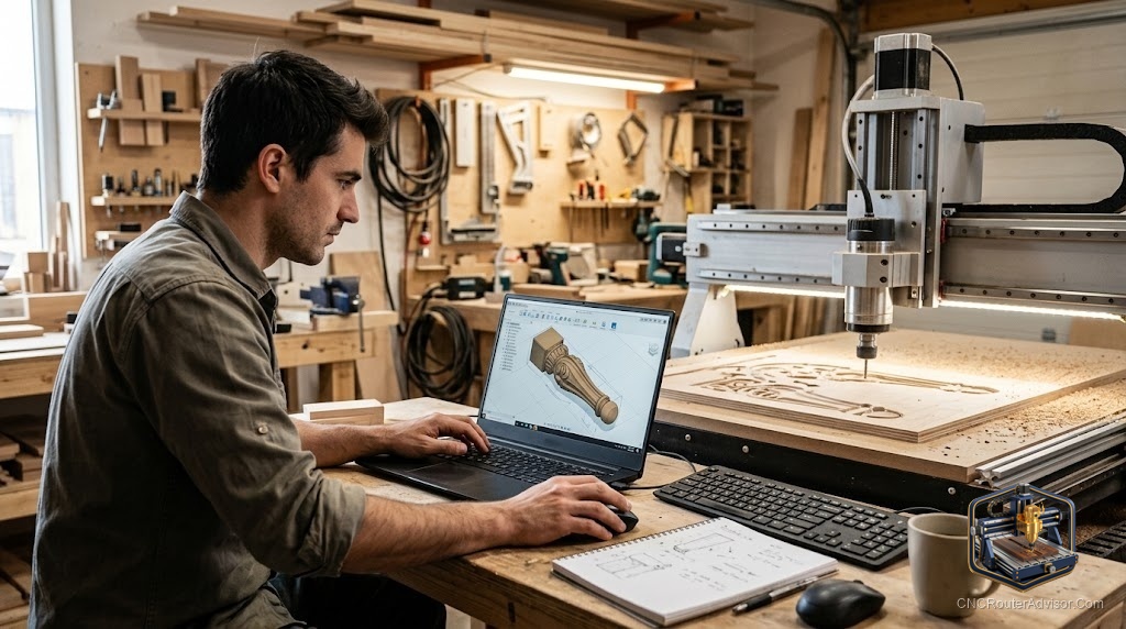
Knowing that a CNC router runs 2D programs is one thing; knowing how to go from an idea to a finished 2D-cut part, step by step, is the practical knowledge that actually gets work done. The 2D CNC routing workflow has several distinct phases, each with its own common mistakes, and understanding what happens at each phase - design, CAM toolpath generation, machine setup, and the cut itself - is what separates operators who produce consistent results from those who are perpetually troubleshooting.
A 2D CNC router workflow is the sequence of steps from a 2D design (flat vector artwork) through CAM software (which generates the toolpaths and G-code) to machine execution (which cuts the part). The key phases are: design creation or import, CAM setup (material thickness, bit selection, toolpath type, cut parameters), G-code export, machine workholding and zero-setting, and program execution.
The short guide: the most common single-source error in 2D CNC routing is incorrect CAM setup - wrong material thickness, wrong bit diameter entered, wrong cut depth, or wrong feed rate. Getting the CAM setup correct before the first cut eliminates 80 percent of the problems that new operators encounter at the machine. Check these four settings before every first run on a new program: material thickness, bit diameter, depth per pass, and feed rate.
Phase 1: Design creation
A 2D CNC design is a vector file: lines, curves, and shapes that define the outlines and internal geometry of the part. Common file formats for CNC import are SVG, DXF, and AI. Common design tools:
- Illustrator / Inkscape (free): Vector design tools that export DXF or SVG directly. Good for text, decorative patterns, and custom shapes.
- Fusion 360: Parametric 2D sketch + CAM in one environment. Preferred for precise mechanical parts.
- VCarve’s built-in design tools: VCarve and Aspire include vector drawing tools sufficient for most sign and furniture work without needing a separate design application.
Important: confirm the design is at the correct physical scale in your CAM software after import. DXF files in particular can import at incorrect scale depending on the unit settings in the originating software. Measure a known dimension in the CAM file after import before proceeding.
Phase 2: CAM setup
This is the most consequential phase. In your CAM software:
-
Set material thickness. Measure the actual material, not the nominal thickness. 3/4 inch plywood is commonly 18mm or 18.5mm, not 19.05mm. Incorrect thickness causes either incomplete through-cuts or excessive plunge into the spoilboard.
-
Select the toolpath type. Profile (on/inside/outside), pocket, drilling, or V-carve for the specific features in the design.
-
Set the bit parameters correctly. Diameter, flute count, and type must match the physical bit you will use. The bit diameter determines offset calculations; entering the wrong diameter shifts your cut.
-
Set depth per pass. For wood on hobby machines, 1 - 2mm per pass is conservative and safe. Optimize upward only after validating the machine handles the initial settings well.
-
Set feed and plunge rates. Start with conservative values (VCarve’s default suggestions for wood are a reasonable starting point). Feed rate errors - too fast for the bit and material - cause bit breakage or burning; too slow causes burning and premature edge wear.
-
Set the Z origin reference. Either material top surface or spoilboard surface. Pick one and be consistent; mixing them between operations causes depth errors.
Phase 3: Machine setup
- Attach the correct bit to the collet, seated correctly, collet tightened to spec.
- Hold the material. Clamps, tabs (planned in CAM), double-sided tape, or vacuum hold-down.
- Set X/Y zero. At the material corner, center, or your CAM’s defined origin point. Use the machine’s probe if available.
- Set Z zero. From the material top surface or spoilboard, consistent with your CAM setting. Use a Z-probe or the paper method.
- Run an air cut first (raise Z by 5-10mm and run the program) to verify the toolpath traces the expected shape without collision.
Phase 4: The cut
Run the program. Stay near the machine for the first few minutes and monitor:
- Feed rate sounds (clean cutting sounds vs. labored or burning)
- Chip color and size (consistent light chips are correct; dust or dark chips indicate problems)
- Material hold-down stability
For a solid bit set for 2D routing work, the Amana Tool 46170-K compression spiral for plywood through-cuts and the SpeTool downcut spiral for top-surface profiles are the core production bits.
Our guide on how to choose a CNC router covers machine selection for 2D routing applications.
The takeaway: a 2D router CNC workflow is design, CAM setup, machine setup, air cut verification, then the real cut. The CAM setup phase is where most errors originate; check material thickness, bit diameter, depth per pass, and feed rate before every new program.
Frequently asked questions
What is the most common mistake in 2D CNC routing? Incorrect CAM setup - wrong material thickness, wrong bit diameter entered, or wrong depth per pass. Verify these four values before every new program.
What is an air cut in CNC routing? Running the program with the Z axis raised several millimeters so the bit doesn’t touch the material, to verify the toolpath traces the correct path without collision or unexpected moves.
What file format does 2D CNC routing use? Design input: DXF, SVG, or AI. Machine output: G-code (.nc, .tap, or .gcode depending on the controller).
What feed rate should I start with for wood? VCarve’s default suggestions for the specific bit and material are a reasonable starting point. Monitor the cut for burning or labored sound and adjust.
What is the correct way to set Z zero in VCarve? Choose either material top surface or spoilboard surface consistently in both the CAM setup and the machine Z-zero procedure. Mixing these two references causes depth errors.
Do I need a probe to set Z zero? No, the paper method (lower the bit until it barely grips a piece of paper, then set Z zero) is adequate for most work. A Z-probe is faster and more consistent.
References
- Vectric, VCarve Pro workflow documentation — https://www.vectric.com/
- Carbide 3D, Carbide Create tutorials — https://docs.carbide3d.com/
- CNC Router Info, beginner workflow guide — https://cncrouterinfo.com/guides/how-to-choose-a-cnc-router/