CNC Router Design Explained: Uses, Setup, and Key Considerations
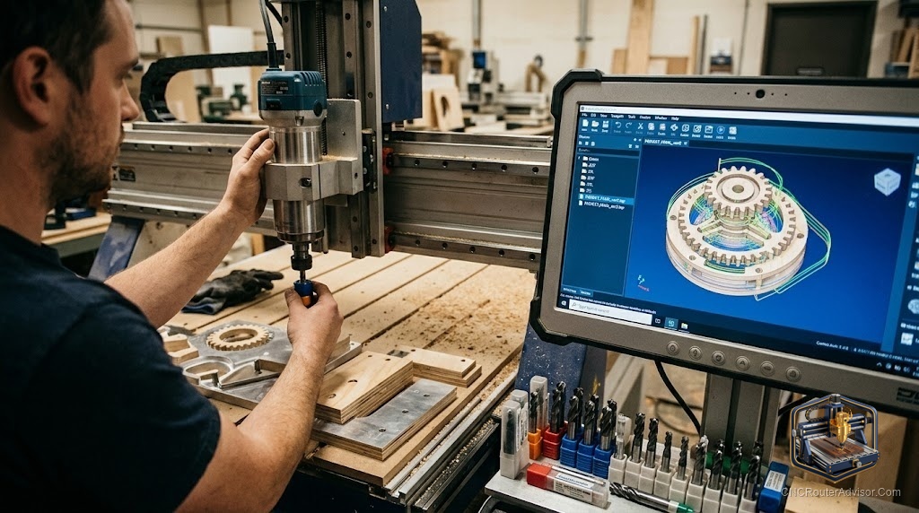
Every finished CNC piece, every carved sign, inlaid box, and relief panel, started as a design on a screen. And this is where a surprising number of projects go wrong before the machine ever spins a bit. A great machine cannot rescue a bad design, and a modest machine can produce stunning work when the design is right. Learning how CNC router design actually works is what turns a pile of ideas into clean, cuttable files.
CNC router design is the process of creating the digital files and toolpaths that tell a CNC router what to cut, from the initial artwork or model through to the G-code the machine runs. It spans vector artwork, 3D models, and the CAM step that turns those into toolpaths. Good design accounts for the bits you own, the material you are cutting, and the limits of your machine, not just how the piece looks on screen.
Short answer: CNC router design means moving from artwork or a model, through CAM toolpaths, to G-code, while designing for real constraints like bit diameter, material, and machine capability. Use vector files such as SVG and DXF for cut and V-carve work and 3D models for relief. Design with your actual tooling in mind, since internal corners, small details, and depths are all limited by the bit.
The design workflow
Most CNC designs move through the same stages:
- Create or source the artwork or model. This might be vector art for a sign, a photo traced to vectors, or a 3D model for relief carving.
- Import into CAD/CAM software. Here you set the material, tool, and dimensions.
- Generate toolpaths (CAM). You assign operations, profile cuts, pockets, V-carves, 3D roughing and finishing, choosing bits and depths.
- Simulate. Preview the toolpaths to catch errors before cutting.
- Export G-code. Output the file your controller runs, with the correct post-processor.
Understanding this chain is what separates a design that cuts cleanly from one that fails on the machine.
File types
- SVG and DXF are vector formats, the backbone of 2D and 2.5D work like signs, cutouts, and V-carving. They define clean lines and curves the machine can follow.
- 3D model formats (such as STL) drive relief carving, where the machine renders a sculpted surface.
- Native CAM project files hold your toolpaths, tools, and settings for re-cutting and editing.
Many makers start from vector artwork and add V-bit and pocket toolpaths to produce signs and decorative pieces.
Designing for your tooling
This is the step beginners skip and regret. The bit determines what you can actually cut:
- Internal corners cannot be sharper than the bit’s radius. A design with tight inside corners needs a small bit or a corner relief.
- Fine detail must be larger than the smallest bit you can run reliably.
- Depth and clearance must fit your Z travel and bit length.
- Cut order and tabs keep parts from shifting or flying loose as they are freed.
Design with the tool in hand, not just the picture in mind.
Design considerations for materials
The material shapes the design too. Wood grain direction affects tear-out, so orient the design thoughtfully. Sheet goods like plywood benefit from tabs to hold parts. Acrylic and plastics need chip-clearing toolpaths. Match your detail and depth to what the material holds cleanly.
Common project designs
CNC design produces a huge range of work: personalized name signs, address plaques, quote signs, and house number plaques; geometric wall art and animal silhouette pieces; engraved cutting boards and bookends; jewelry boxes, piggy bank boxes, and cribbage boards; and shelves and small furniture. Most begin as SVG or DXF vectors, cut with V-bits for lettering and straight bits for clearing and profiling.
Key considerations before you cut
- Set the right material and tool in your CAM so speeds, feeds, and depths make sense.
- Simulate every job to catch gouges, missed tabs, or collisions.
- Check dimensions and origin so the design lands where you expect on the stock.
- Plan tabs and cut order to hold parts secure until the end.
- Match ambition to machine, keeping detail within what your bits and rigidity can deliver.
The bottom line
CNC router design is the bridge between an idea and a finished piece, and it rewards designing for reality: your bits, your material, and your machine. Move deliberately from artwork or model through CAM toolpaths to simulated, verified G-code, and account for bit radius, detail size, and material behavior along the way. Do that and even a modest machine produces clean, professional work. Skip it and the best machine in the world will still cut a flawed file faithfully.
FAQ
What is CNC router design? The process of creating the digital files and toolpaths that tell a router what to cut, from artwork or a 3D model through CAM to the final G-code.
What file types do CNC routers use? Vector formats like SVG and DXF for 2D and V-carve work, 3D model formats like STL for relief, and native CAM project files for toolpaths.
Do I need to design around my bits? Yes. Internal corners cannot be sharper than the bit radius, and fine detail must exceed your smallest reliable bit. Design with your tooling in mind.
What software do I use to design for CNC? CAD/CAM software such as Easel, Carbide Create, VCarve, Aspire, Fusion 360, or Carveco, matched to whether you do 2D, 2.5D, or 3D work.
Why should I simulate before cutting? Simulation catches gouges, collisions, missed tabs, and wrong depths before they waste material or break a tool.
What are tabs? Small bits of uncut material left to hold a part in place until the job finishes, so it does not shift or come loose mid-cut.
Can I design from a photo? Yes. You can trace a photo into vectors for cutting or V-carving, or use relief software to turn images into 3D carvings.
References
- BubbleRelief, CNC router projects for beginners: https://bubblerelief.com/cnc-router-projects-for-beginners/
- Instructables, DIY CNC router plans and how to build: https://www.instructables.com/DIY-CNC-Router-Plans-How-to-Build/