STL File CNC Router: What an STL File Is and How It Works with Your Machine
The first time someone hands you a downloaded STL file and says “just cut this on your CNC router,” the honest answer is: it is not that simple, and also it kind of is, once you understand what an STL is and what step your CAM software needs to take before the machine can cut it. The gap between a downloaded STL and a finished part is one workflow step, and clearing up the confusion about that step saves beginners a lot of wasted time.
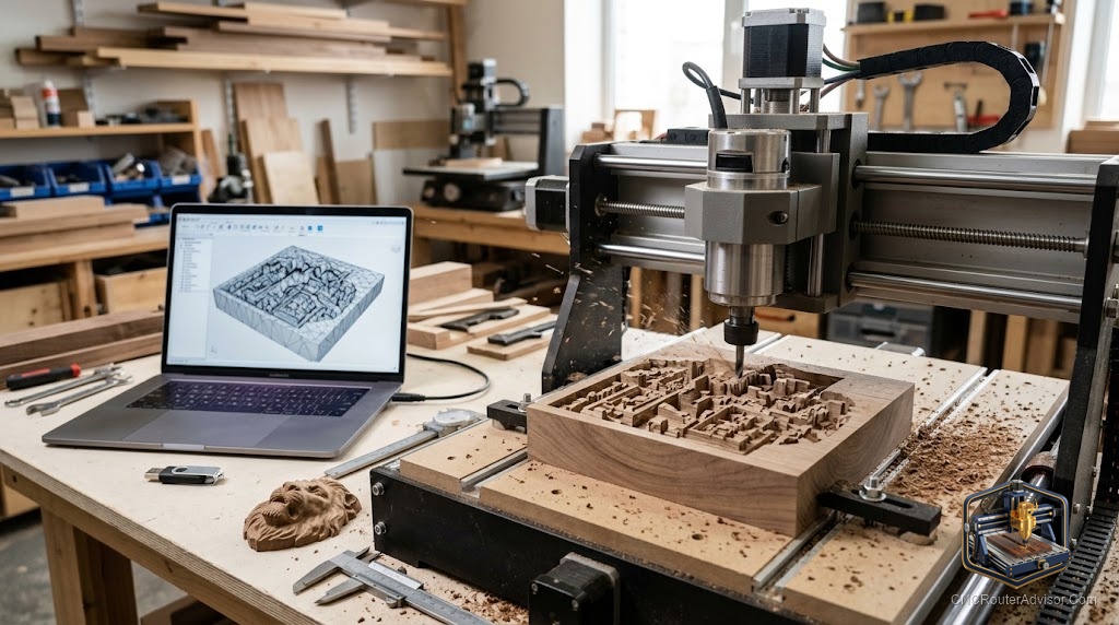
An STL file is a 3D geometry format that describes a surface as a mesh of triangles. It is the format most common in 3D printing, and it works in CNC routing too, but with a critical difference: a 3D printer reads the STL directly, while a CNC router reads G-code, a list of coordinate moves. To cut from an STL file, you import the STL into CAM software, which generates the toolpaths and outputs the G-code your machine runs. The STL is the design source; the G-code is the machine instruction.
The short version of the workflow: download or create an STL, import it into your CAM program, set up the 3D roughing and finishing toolpaths, export the G-code, load it onto the machine, and cut. Each step has choices to make (which bit, what step-over, how many passes), but the chain is straightforward once you have done it once.
What an STL actually is, and why it is useful for CNC
STL stands for stereolithography, the 3D printing process it was originally designed for, but the format has become the lingua franca of 3D geometry across many manufacturing tools. An STL file describes the outer surface of a 3D shape as a mesh of tiny triangles. The resolution of that mesh determines how smooth curves look when cut: a high-resolution STL with many small triangles produces smoother curved surfaces than a low-resolution one with larger triangles.
For CNC routing, STL files are most useful for 3D carving work: relief carvings, topographic maps, carved signs with dimensional depth, decorative panels, and anything with a non-flat surface. A flat 2D design (a sign with flat text, a profiled edge, a simple pocket) is better served by a vector file (SVG, DXF) rather than an STL, because STL is a 3D format and using it for flat work adds unnecessary complexity. If the project has depth that varies across the surface, STL is the right input format.
From STL to G-code: the CAM step
This is the step that confuses most beginners. You cannot just load an STL file into your CNC machine’s controller. The controller reads G-code (a series of coordinate moves, speeds, and spindle commands), and an STL file contains surface geometry, not machine instructions.
CAM software bridges that gap. You import the STL, define the stock size (the blank material you are cutting from), select the toolpaths (typically a 3D roughing pass to remove bulk material quickly followed by a 3D finishing pass at smaller step-over for smooth detail), choose the bits for each pass, and export G-code. The CAM software handles all the geometry calculations, working out where the bit needs to go at each point to produce the surface the STL describes.
For STL-based 3D carving, popular CAM choices include Carbide Create Pro’s 3D toolpath feature, VCarve Pro with its 3D toolpaths module, and Fusion 360’s CAM workspace. Each has different learning curves and price points, but all of them import STL files and output compatible G-code for most machines.
Key CAM settings for cutting from STL files
Three settings make the most difference in the quality of a CNC-cut STL.
Step-over on the finishing pass. This is the spacing between adjacent passes of the finishing bit, expressed as a percentage of the bit’s diameter. A smaller step-over (10 percent or less for a fine finish) produces a smoother surface because the cusp height between passes is smaller. A larger step-over runs faster but leaves visible ridges. For decorative carvings, a step-over of 5 to 10 percent on the finishing pass is common. Calculate your time before cutting: fine step-overs on large surface areas take hours.
Ball-nose vs. flat-end finish bit. A ball-nose bit is standard for 3D finishing because its rounded tip follows curved surfaces more smoothly than a flat end mill. The diameter depends on the detail you need: smaller bits follow fine detail; larger bits run faster over broad surfaces.
Stock orientation and zero. Set your Z-zero consistently and clamp the stock flat and securely. A 3D toolpath that spans the full height of the carving must know exactly where the top of the stock is, and any error in Z-zero results in either cutting too deep (ruining the workpiece) or not deep enough (leaving a surface that does not match the design).
Where to find good STL files for CNC routing
The internet has a large and growing library of STL files originally made for 3D printing, but many translate well to CNC carving. Good sources include Thingiverse, Cults3D, MyMiniFactory, and dedicated CNC sites like Design Bundles and CNCFileStore. When evaluating an STL for CNC carving, check the mesh resolution (higher is better for smooth curves), confirm the design has no internal voids or overhangs that a bit cannot reach, and check that the depth of the design is achievable with your machine’s Z clearance and your material thickness.
Files designed specifically for CNC carving are sold on sites like Design Bundles and Etsy CNC stores, and they come with the right geometry for cutting rather than printing, which saves cleanup time in CAM.
Our guide on how to choose a CNC router helps confirm your machine’s Z clearance and rigidity for 3D carving work before committing to a complex STL file.
The takeaway: an STL file is the design input for 3D CNC carving, not a machine-ready file. Import it into CAM software, set up your 3D toolpaths, export G-code, and cut. The workflow has one extra step compared to 2D cutting, but it opens up dimensional carving that flat files cannot produce.
Frequently asked questions
Can a CNC router read STL files directly? No. STL files contain 3D geometry, and CNC machines run G-code. CAM software converts the STL to G-code toolpaths that the machine can follow.
What CAM software works with STL files? Carbide Create Pro, VCarve Pro, Fusion 360, and many others. Each imports STL and outputs G-code compatible with most CNC router controllers.
What is the best bit for cutting from an STL file? A ball-nose bit for the 3D finishing pass, because its rounded tip follows curved surfaces smoothly. A flat-end mill or V-bit is used for the roughing pass to remove bulk material quickly.
What is step-over and why does it matter? Step-over is the spacing between adjacent finishing passes as a percentage of the bit diameter. Smaller step-over (5 to 10 percent) produces smoother surfaces; larger step-over runs faster but leaves visible ridges between passes.
Where do I find STL files for CNC carving? Thingiverse, Cults3D, MyMiniFactory for free files, and Design Bundles, CNCFileStore, and Etsy CNC stores for files designed specifically for cutting.
What makes an STL file unsuitable for CNC routing? Internal voids the bit cannot reach, overhangs requiring undercuts, very thin walls, or very low mesh resolution that produces choppy curves. Design files made for 3D printing sometimes have these issues, while CNC-specific files usually do not.
References
- Carbide 3D, “3D Toolpaths with Carbide Create Pro” — https://docs.carbide3d.com/
- Vectric, “VCarve Pro 3D Toolpaths” — https://www.vectric.com/products/vcarve-pro
- All3DP, “CNC Router Software Guide” — https://all3dp.com/2/cnc-router-software-guide/