Components for Routing and CNC Machining Explained: Uses, Setup, and Key Considerations
When you look at a CNC router as a whole, it can seem like a single complicated object. Break it into its components, though, and it becomes something you can actually understand, evaluate, and improve. Every routing and CNC machining setup is an assembly of parts, each with a job, and knowing what those parts do turns a mysterious machine into a set of understandable systems. This guide walks through the components that make routing and CNC machining work.
The frame and structure
Everything starts with the frame, because it is what holds all the precision together. Built from a steel frame or heavy aluminum extrusion, the structure provides the rigidity that keeps the cutter where it belongs. Frame rigidity is the foundation of cut quality, since any flex shows up as chatter, poor finish, and inaccuracy. When people ask why one machine cuts cleaner than another, the answer often lives here.
The motion system
The motion system is what moves the cutter with precision across the three axes, the X axis for left and right, the Y axis for front and back, and the Z axis for depth. It is built from several components working together:
- Drive mechanism, such as ball screws, lead screws, or timing belts, which converts motor rotation into linear movement.
- Linear rails or guides, which keep that movement straight and true.
- Stepper motors, which drive the axes under the controller’s command.
Together these determine accuracy, repeatability, and speed. Screws favor precision, belts favor lower cost and higher speed on lighter machines.
The spindle
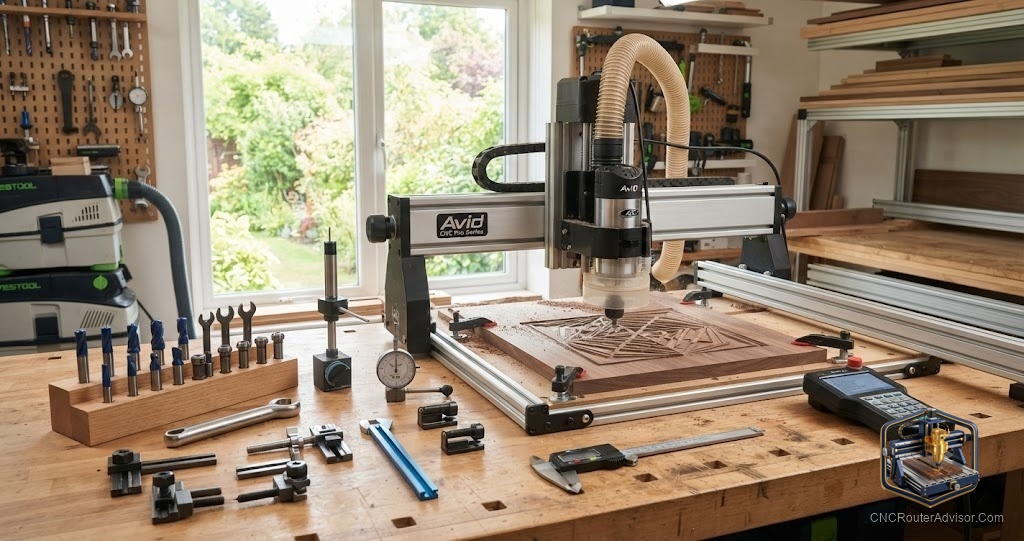
The spindle is the component that actually cuts, spinning the tool at high speed. It might be a trim router pressed into service, a DC spindle, or a VFD spindle with real speed control. The spindle’s power and speed range decide what materials you can cut and how aggressively. It holds the cutting tool through a collet, and the quality of that collet directly affects accuracy through tool runout.
The control system
The control system is the brain that ties everything together. A controller, often a GRBL controller on hobby machines, reads G-code and sends the signals that drive the stepper motors. Software on a computer generates that G-code from your design. This is where a digital design becomes physical motion, and it is as much a part of the machine as any piece of metal.
Workholding and support components
Surrounding the machine are the components that make it usable in practice. Workholding, including a spoilboard, clamps, and hold-down systems, keeps material secure so it cannot shift during a cut. Dust collection clears chips and protects your lungs. Tooling, the bits and collets, matches the cut to the material. These support components are easy to overlook but essential to good results.
How the components work together
The key insight is that these parts form a system, and the weakest one limits the whole. A rigid frame is wasted if the workholding lets material move. A powerful spindle cannot save a flexing gantry. Precise screws mean little if the collet has runout. Understanding routing and CNC machining as an assembly of interdependent components is what lets you diagnose problems and choose upgrades wisely, because you can trace a symptom back to the part responsible.
Setup and key considerations
When you set up or evaluate a machine, go component by component. Confirm the frame is rigid and square. Check that the motion system is clean, adjusted, and free of backlash. Make sure the spindle suits your materials and the collet runs true. Verify the control system and software fit together. And build solid workholding and dust collection around it all. Approach the machine this way and it stops being intimidating, becoming instead a set of understandable systems you can keep in tune for years.