CNC Router Description: Anatomy, Components, and How the Parts Work Together
If you have ever tried to describe a CNC router to someone who has never seen one, you know it is harder than it sounds. It is part robot, part woodworking tool, part computer. The clearest way to describe it is not with a single sentence but by walking through the machine part by part, because a CNC router is really a set of components working in concert, and once you can name each part and say what it does, the whole machine stops being a mysterious box and becomes something you can reason about, buy wisely, and troubleshoot.
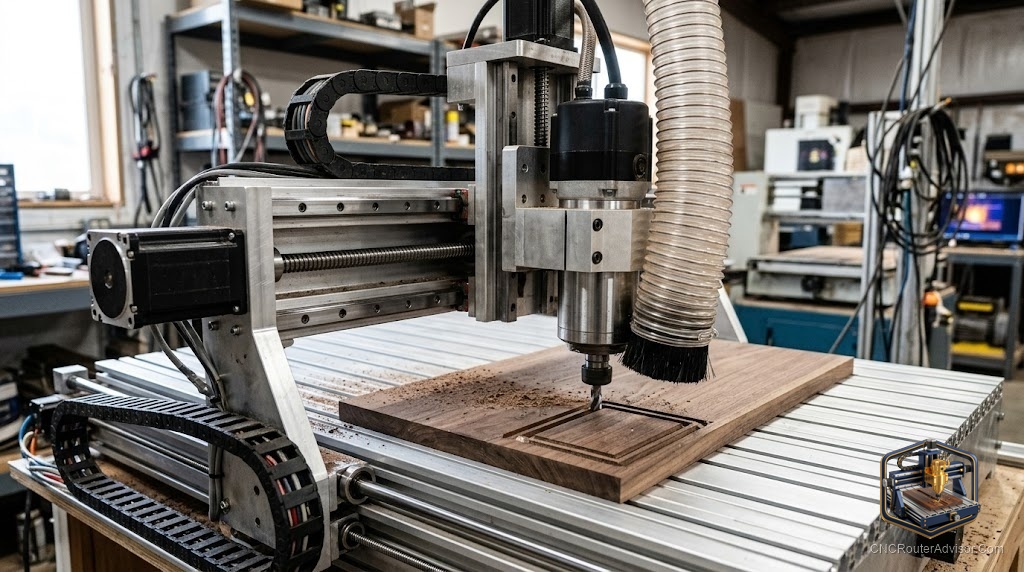
A CNC router can be described as a computer-controlled machine with a rigid frame, a moving gantry carrying a spinning cutting tool, a motion system that positions that tool precisely along multiple axes, and a controller that translates a digital design into physical movement. This description, an assembly of cooperating parts, is more useful than a one-line definition when you actually want to understand or evaluate a machine.
Short version: describe a CNC router by its anatomy. Frame and bed for rigidity and support, gantry and axes for movement, spindle and tooling for cutting, and controller and software for the brains. Understand those four groups and you can describe, compare, or diagnose any router you meet.
The structure: frame and bed
Everything starts with the structure, because it decides how good the cuts can be. The frame is the machine’s skeleton, made of steel, aluminium extrusion, or on hobby machines sometimes a mix, and its rigidity sets the ceiling on cut quality. A flexible frame allows the tool to deflect under load, which shows up as chatter, uneven depth, and mismatched parts. The bed or table is the surface the material sits on, often fitted with a replaceable spoilboard, T-slots, or a vacuum system to hold work down. A common description shorthand: the heavier and stiffer the structure, the more capable and consistent the machine.
The movement: gantry and axes
On top of the structure sits the moving part. The gantry is the bridge that spans the bed and carries the cutting head, sliding along the machine’s length. Movement happens along three axes: X (typically left to right), Y (front to back), and Z (up and down, controlling cut depth). Combining motion across all three lets the tool reach any point in the work area and control how deep it cuts, which is what enables both flat cutting and 3D carving.
Driving that movement is the motion system: motors turning belts, lead screws, ball screws, or rack and pinion. This is where machines differ most in accuracy. Belts are common on small hobby machines; lead screws and ball screws suit mid-range precision; rack and pinion handles large machines over long spans. Describing a router’s motion system tells you a lot about what it is built to do.
The cutting: spindle and tooling
At the business end is the part that removes material. The spindle or router holds and spins the cutting bit at high speed. It ranges from a compact trim router on hobby machines to a dedicated VFD spindle, air-cooled or water-cooled, on more serious ones. The collet grips the bit inside the spindle, and the bit itself, chosen for the material and cut, does the actual cutting. When people describe a router as powerful or precise at the cut, they are really describing the spindle and how truly it holds the tool.
The brains: controller and software
None of the hardware means anything without direction. The controller is the electronic brain that reads G-code and commands the motors to move each axis. The software side has two roles: design software (CAD) to create the shape, and CAM software to convert that design into toolpaths and G-code the controller can execute. A complete description of any CNC router includes not just its metal and motors but the software it runs, because a capable machine with software you cannot drive is not a capable machine for you.
How the parts work together
The description comes alive when you follow one cut through the whole assembly. The software produces G-code. The controller reads it and signals the motors. The motion system moves the gantry and head along the X, Y, and Z axes. The spindle spins the bit, held true by the collet, and the frame and bed hold everything rigid and the work still while material is removed. Each part depends on the others: a strong spindle on a weak frame still chatters, and a rigid frame with a poor controller still cuts badly. That interdependence is the single most useful thing to understand when describing, buying, or fixing a CNC router.
The verdict
The most useful CNC router description is anatomical: name the parts and say how they cooperate. Frame and bed give rigidity and support, gantry and axes provide precise movement, spindle and tooling do the cutting, and controller and software supply the direction. Because the parts are interdependent, judge a machine as a whole system rather than by any single impressive spec, and you will describe, compare, and troubleshoot routers with real confidence.
Three things to remember:
- Describe a CNC router by four groups: frame and bed, gantry and axes, spindle and tooling, and controller and software.
- The frame sets the ceiling on quality, the motion system sets accuracy, and the spindle plus collet decide the cut; none works well without the others.
- Software is part of the machine’s description, because a router is only as usable as the CAD and CAM workflow that drives it.
FAQ
How would you describe a CNC router in simple terms? As a computer-controlled machine with a rigid frame, a moving gantry carrying a spinning cutting tool, a motion system that positions the tool along the X, Y, and Z axes, and a controller that turns a digital design into physical movement.
What are the main components of a CNC router? The frame, the bed or table, the gantry, the motion system (motors with belts, screws, or rack and pinion), the spindle or router, the collet and bit, and the controller with its software.
What are the axes on a CNC router? X (usually left to right), Y (front to back), and Z (up and down, controlling cut depth). Coordinated movement across all three lets the tool reach any point and cut to any depth in the work area.
What does the spindle do? The spindle holds and spins the cutting bit at high speed to remove material. It may be a compact trim router or a dedicated VFD spindle, air-cooled or water-cooled on more capable machines.
What is the role of the controller? The controller is the machine’s electronic brain. It reads the G-code produced by CAM software and commands the motors to move each axis, coordinating the whole cut.
Why does the frame matter so much in describing a machine? The frame’s rigidity sets the ceiling on cut quality. A flexible frame lets the tool deflect, causing chatter and inconsistency, so a heavier, stiffer structure generally means a more capable machine.
Is software part of a CNC router? Effectively yes. Design (CAD) and CAM software create the shape and generate the G-code the controller runs. A full description of a router includes the software workflow that drives it.
References
- CNC Router Info, How to Choose a CNC Router (components and selection): https://cncrouterinfo.com/guides/how-to-choose-a-cnc-router/
- 731 Woodworks, CNC Machines for Small Woodworking Shops (machine anatomy in context): https://www.731woodworks.com/731-blog/best-cnc-machines-for-small-woodworking-shops-in-2025-beginner-to-pro-picks