CNC Router Components: The Parts That Make Up a Machine
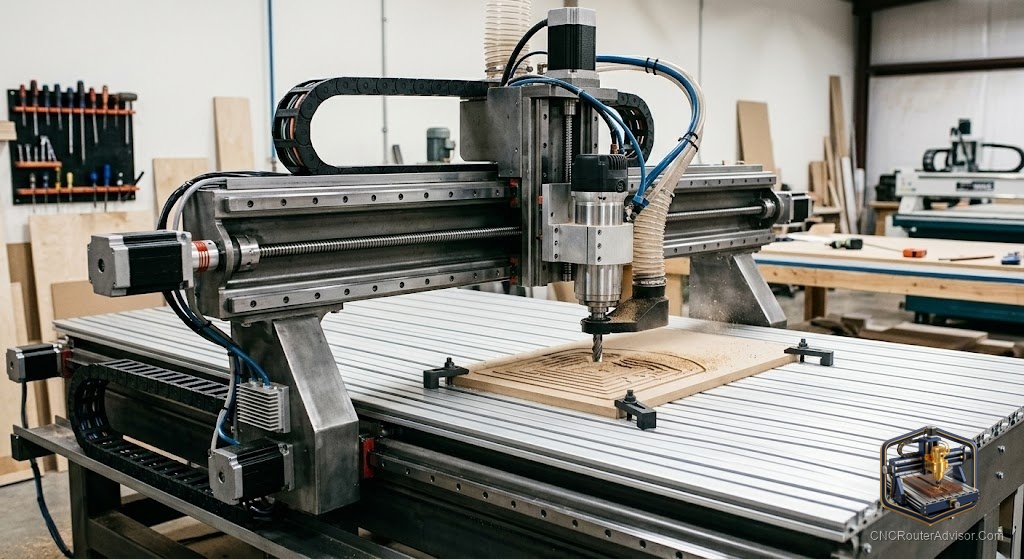
Every CNC router, from a $300 desktop kit to a $100,000 industrial machine, is built from the same functional building blocks. Understanding these components, what each does and how they interact, is genuinely useful whether you are buying a machine, upgrading one, troubleshooting a problem, or building your own. It turns a spec sheet from a wall of jargon into a meaningful description of what a machine can do, and it helps you understand why two machines at very different prices perform so differently.
CNC router components are the functional building blocks that make up the machine: the frame and gantry (structure), the motion system (rails and drive), the motors, the spindle or router (the cutting tool), the controller and electronics, and the software that drives it. Each component affects the machine’s rigidity, accuracy, speed, and material capability.
The short answer on why this matters: a machine’s performance is determined by how well its components work together, especially the frame rigidity, drive system, and spindle. When comparing machines, focus on these core components rather than headline numbers, because they determine what the machine can actually cut and how accurately.
The structural components
Frame (base). The foundation that everything mounts to. Frame material, welded steel (most rigid), aluminum extrusion (common, versatile), or plywood (budget), largely determines the machine’s overall rigidity and therefore its material capability.
Gantry. The bridge that carries the spindle across the work area (on moving-gantry machines) or holds it fixed (on moving-table machines). A rigid gantry resists flex and deflection during cutting. Gantry design and mass are major factors in cut quality.
Bed / spoilboard. The work surface where material is held. Often a sacrificial spoilboard over a T-slot or vacuum table.
The motion system
Linear guides (rails). How the axes move smoothly and accurately:
- Profile linear rails with recirculating ball bearing blocks: the most rigid and precise, used on quality machines.
- V-wheels on extrusion: common on hobby machines, lower cost, less rigid.
- Round shafts with linear bearings: a middle option on some machines.
Drive system (transmission). Converts motor rotation into linear motion:
- Ball screws: highest precision and rigidity, backlash-free, higher cost.
- Lead screws: good value, more rigid than belts.
- Rack and pinion: used on large machines for long travel and speed.
- Timing belts: inexpensive and fast, but flex under load.
The motion and power components
Motors.
- Stepper motors (NEMA 17/23/34): the standard on most hobby and prosumer machines; move in precise steps, open-loop by default.
- Servo motors: used on industrial machines; closed-loop feedback for speed, accuracy, and torque under load.
- Closed-loop steppers: steppers with encoders that add position feedback and reliability.
Spindle or router (the cutting tool).
- Trim router (Makita/DeWalt): cheap, easy to replace, common on hobby machines.
- VFD spindle (air- or water-cooled, 0.8kW to 11kW+): quieter, more powerful, variable speed, longer life. The upgrade that most improves capability and noise.
- Collet: holds the bit in the spindle (ER11, ER20, etc.), sized to bit shanks.
The control components
Controller (control board). The electronics that interpret G-code and drive the motors, GRBL (hobby standard), or more capable industrial controllers (Mach3/Mach4, LinuxCNC, or proprietary controls). It coordinates all axes and the spindle.
Drivers. Power the motors according to controller signals (sometimes integrated on the control board).
Limit / homing switches. Define the machine’s travel limits and reference position for repeatable coordinates.
Power supply and wiring. Provide and distribute power to motors, spindle, and electronics.
Emergency stop and safety circuits. Cut power immediately for safety, essential components, not optional.
The software layer
While not hardware, software is a functional component of the system:
- CAD: designs the part.
- CAM: generates toolpaths and G-code.
- Control/sender software: streams G-code to the controller (Candle, UGS, CNCjs, Carbide Motion, Mach3).
How the components work together
Cutting quality emerges from the interaction of components: a rigid frame and gantry hold the spindle steady; precise linear rails and a stiff drive system position it accurately; capable motors move it reliably under load; a powerful spindle cuts cleanly; and the controller and software coordinate it all. A weakness in any one, most often a flexible frame or a loose drive system, limits the whole machine, which is why rigidity and drive quality dominate real-world performance.
The verdict
Every CNC router is built from the same core components, frame and gantry, motion system (rails and drive), motors, spindle, controller, and software, and understanding them turns spec sheets into meaningful comparisons. When buying or upgrading, focus on the components that most affect performance: frame and gantry rigidity, the drive system (ball screw vs. lead screw vs. belt), the linear guides, and the spindle. These determine what a machine can cut and how accurately, far more than any headline number.
Three takeaways: the core components are frame/gantry, motion system, motors, spindle, controller, and software, and they must work together; rigidity (frame, gantry, linear rails) and the drive system are the biggest determinants of real performance; and the spindle choice (trim router vs. VFD) most affects cutting power, noise, and material range.
FAQ
What are the main components of a CNC router? The frame and gantry (structure), the motion system (linear rails and drive), the motors, the spindle or router, the controller and electronics, and the software (CAD/CAM/sender) that drives it.
Which CNC router component matters most for cut quality? Rigidity, primarily the frame, gantry, and linear rails, together with a stiff drive system (ball screw over belt). A flexible machine chatters and cuts poorly regardless of other specs.
What is the difference between a spindle and a trim router? A trim router (Makita/DeWalt) is cheap and easily replaced. A VFD spindle is quieter, more powerful, supports variable speed, and lasts longer, at higher cost. The spindle upgrade most improves capability.
What drive systems do CNC routers use? Ball screws (highest precision), lead screws (good value), rack and pinion (large machines, long travel), and timing belts (inexpensive, fast, flex under load). The drive system strongly affects rigidity and accuracy.
What is a CNC router controller? The electronics that interpret G-code and drive the motors and spindle. GRBL is the hobby standard; Mach3/Mach4, LinuxCNC, and proprietary controls run more capable machines.
What are linear guides on a CNC router? The components that let axes move smoothly and accurately: profile linear rails with ball-bearing blocks (most rigid), V-wheels on extrusion (common, lower cost), or round shafts with bearings (middle option).
What motors do CNC routers use? Stepper motors (NEMA 17/23/34) on most hobby and prosumer machines, servo motors on industrial machines for closed-loop accuracy, and closed-loop steppers that add position feedback for reliability.
References
- CNCRouterInfo, How to Choose a CNC Router (components and their roles): https://cncrouterinfo.com/guides/how-to-choose-a-cnc-router/
- Sienci Labs, Common CNC Terms (frame, gantry, drive system, controller): https://resources.sienci.com/view/lm-common-cnc-terms/
- Onefinity CNC, Machine Specifications (ball screws, motors, controller components): https://www.onefinitycnc.com/
- Carbide 3D, How a CNC Works (structure, motion, spindle, control): https://carbide3d.com/learn/
- PrintNC, Components and Bill of Materials (frame, rails, drive, electronics): https://wiki.printnc.info/